1. Introduction: Solar Rail as an Independent Structural Subsystem
In EPC solar projects, the rail system is not just a component of the mounting structure — it is an independent structural subsystem responsible for load distribution and mechanical stability.
Unlike roof hooks or clamps, the solar rail defines the primary structural span system that determines how wind and snow loads are transferred through the PV array.
EPC contractors searching for a solar mounting system supplier, solar rail manufacturer China, or PV mounting rail supplier require rail-specific engineering knowledge rather than general mounting system explanations.
This guide focuses exclusively on solar rail structural engineering as an independent subsystem.
2.Solar Rail System Engineering Boundary Definition
This article defines the solar rail system strictly as an independent structural engineering subsystem responsible for load bridging between discrete roof anchoring points in photovoltaic mounting systems.
All references to roof hooks, clamps, fasteners, or general PV mounting systems are strictly limited to interface-level descriptions and are not part of the rail system scope.
This strict boundary ensures that all engineering principles described in this article apply exclusively to rail structural behavior, not to any other PV mounting component or system layer.
3. Rail System Engineering Role
The solar rail system operates as the primary structural spine of PV installations.
It is responsible for:
| Engineering Function | Descriere |
|---|---|
| Structural spanning | Bridges between roof attachment points |
| Load redistribution | Transfers wind/snow loads across system |
| Module alignment control | Maintains PV geometry stability |
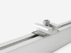
| System integration interface | Connects hooks, clamps, and fasteners |
👉 Unlike other components, rail design determines the structural behavior of the entire PV array.
The solar rail system functions as a continuous structural beam model within PV mounting systems, where discrete support points (roof hooks or anchors) act as boundary conditions and clamps act as distributed load interfaces.
4. Rail Engineering Design Parameters
4.1 Structural Load Definition
Rail systems must be designed based on:
- Wind pressure distribution zones
- Snow accumulation risk levels
- Roof structural spacing constraints
- System elevation and tilt geometry
Rail span and profile selection must be validated based on structural load calculations rather than visual or cost-based selection.
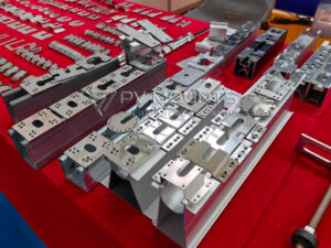
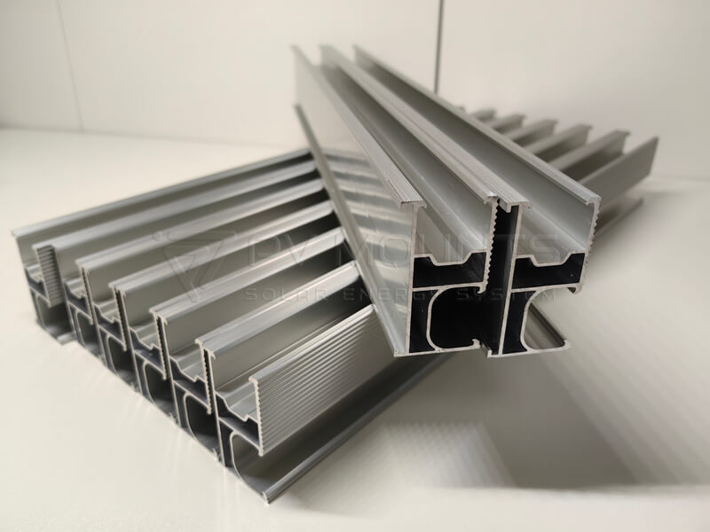
4.2 Cross-Section Engineering (Core Design Factor)
Rail geometry determines:
- Moment of inertia (deflection resistance)
- Load span capability
- Clamp compatibility tolerance
- Hook connection stability
Different rail profiles are required for different EPC project scales.
4.3 Material & Surface Engineering
Common engineering materials:
- Aluminum alloy 6005-T5 / 6063-T5
- Anodized surface layer for corrosion protection
- Optional high-thickness profiles for coastal environments
5. Rail System Load Path
| Stage | Load Transfer Path |
|---|---|
| 1 | Solar module load |
| 2 | Mid / end clamp |
| 3 | Solar rail system |
| 4 | Roof hook / L-foot |
| 5 | Roof structure (purlin / rafter) |
👉 This defines the rail as the central structural transfer element
6. Rail System Compatibility Engineering
The solar rail must be engineered to interface with:
- Roof hook systems (structural anchoring)
- Clamping systems (module fixation)
- Grounding clips (electrical bonding continuity)
- Fasteners (mechanical locking integrity)
Rail compatibility defines system reliability more than any single component.
| System Element | Engineering Role | Scope in This Article |
|---|---|---|
| Solar Rail | Structural beam | FULL focus |
| Roof Hook | Support point | Only interface mention |
| Clemă | Load transfer point | Interface only |
| Fastener | Fixing element | Not covered |
7. Rail Engineering Decision Logic (EPC Workflow)
- Define structural load conditions
- Determine roof attachment spacing
- Select rail cross-section geometry
- Validate clamp compatibility
- Confirm system deflection limits
8. Common EPC Rail Design Mistakes
- Treating rails as non-structural components
- Ignoring span deflection limits
- Using mismatched hook-rail systems
- Overlooking environmental corrosion factors
- Selecting based on price instead of engineering data
Rail Structural Risk Consideration
Poor rail system design may lead to:
- Excessive deflection under wind load
- Clamp misalignment
- Roof hook overload failure
- Long-term structural fatigue
Rail system integrity directly determines PV system lifespan.
9. EPC Procurement Considerations
EPC contractors should evaluate:
- Structural certification requirements
- Rail system consistency across project scale
- Compatibility with full PV mounting architecture
- Installation efficiency and labor cost impact
- Long-term deformation resistance
10. PV MOUNTS Rail Engineering Capability
PV MOUNTS provide:
- Engineering-based rail system design
- OEM / ODM customization
- EPC project structural support
- Full PV mounting system integration solutions
11.FAQ
Because it defines load transfer and system geometry.
Both are critical, but rail defines system-level behavior.
Cross-section geometry and aluminum alloy grade.
No, they must be engineered per project conditions.
To distribute structural loads across the PV system.
Poor rail design leads to deformation and instability.
Indirectly via grounding clips and system bonding design.
Due to strength-to-weight ratio and corrosion resistance.
Yes, based on EPC engineering requirements.
For scalable manufacturing, customization, and cost efficiency.
12. Conclusion
The solar rail system is an independent structural subsystem that defines the mechanical behavior of PV mounting systems.
Proper rail engineering ensures structural stability, load distribution efficiency, and long-term system reliability under real EPC project conditions.
PV MOUNTS supports global EPC contractors as a solar rail manufacturer China, PV mounting rail supplier, and solar mounting system supplier, delivering engineering-driven rail system solutions for international solar projects.