
1. Introduction
Solar roof hooks are a critical structural component in tile roof photovoltaic mounting systems. They connect aluminum mounting rails to roof rafters and ensure that loads from solar panels are safely transferred to the building structure.
Proper spacing between roof hooks is essential for maintaining the structural stability of the solar mounting system. If hooks are spaced too far apart, mounting rails may experience excessive bending stress, leading to long-term structural fatigue or system instability.
For solar installers, EPC contractors, and system designers, understanding roof hook spacing and load distribution is an important part of engineering design. This guide explains the structural principles behind roof hook spacing, including environmental loads, rail bending behavior, and typical installation practices.
2. What Is Tile Roof Hook Spacing and Why It Matters
Tile roof hook spacing refers to the distance between individual hooks mounted on the roof aligned with the rafters. Correct spacing:
- Ensures even load distribution from solar panels to roof structure
- Prevents rail bending and panel misalignment
- Provides safe installation under snow and wind load
- Reduces risk of tile cracking or damage
Pro Tip: Spacing decisions should always factor in panel size, roof slope, tile type, and environmental loads.
3. Step-by-Step Guide to Calculating Hook Spacing
31. Assess Dead Load and Live Load
- Dead load: weight of panels, rails, and hooks
- Live load: temporary forces like installers, maintenance, or snow accumulation
- Formula: Hook load = (Panel weight + Rail weight + Safety Factor) ÷ Number of hooks
3.2. Wind Uplift and Snow Load Considerations
- Wind uplift can pull panels away from roof; hooks must resist this force
- Snow load adds vertical pressure; heavy snow regions require closer hook spacing
- Tip: Use Eurocode EN 1991‑1‑3 for snow and EN 1991‑1‑4 for wind load calculations
3.3. Edge and Corner Hook Spacing
- Hooks near roof edges and corners require tighter spacing to resist uplift
- Typical edge spacing = 600–800 mm, interior = 1000–1200 mm depending on load
4. Structural Load Path in Tile Roof Solar Mounting Systems
Understanding how loads travel through a solar mounting system is the first step in structural design.
In tile roof solar installations, loads follow this path:
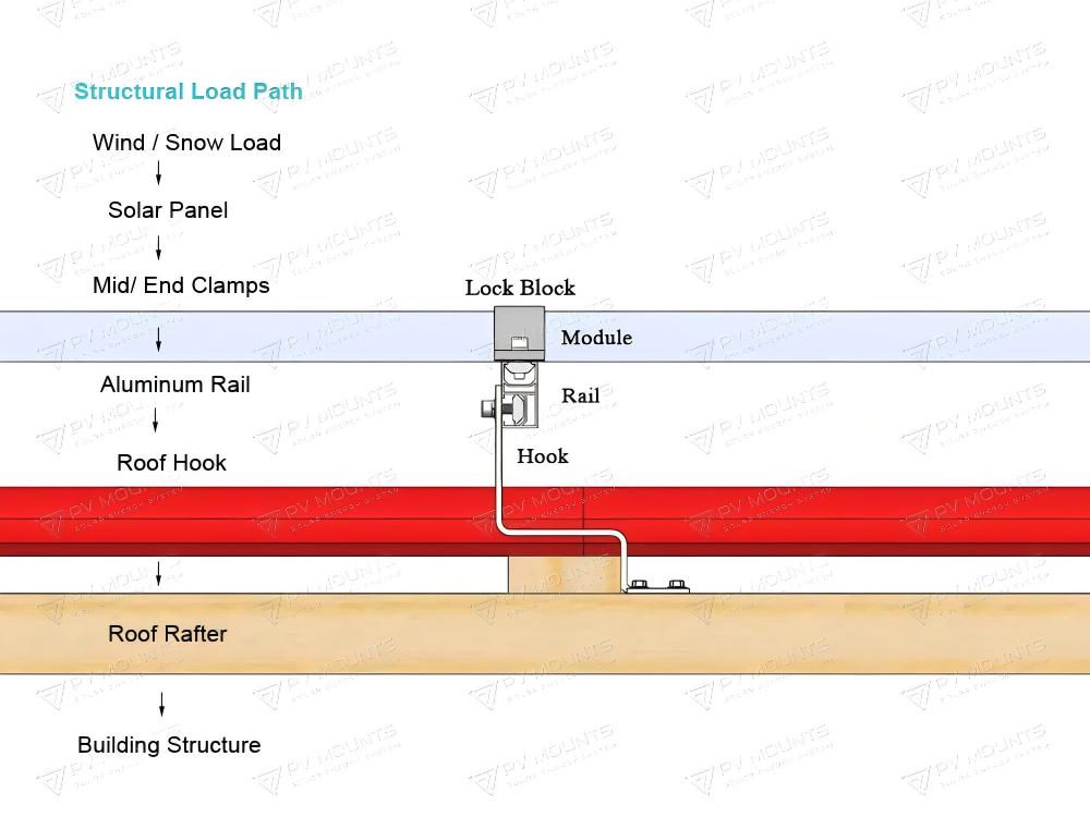
Roof tiles themselves do not carry structural loads. Instead, roof hooks bypass the tile layer and anchor directly into the structural rafters beneath the roof.
This load transfer system ensures that wind and snow loads are safely carried by the building structure.
5. Environmental Loads Acting on Solar Mounting Systems
Solar mounting systems must be designed to resist environmental loads over their entire service life.
The most important loads affecting rooftop solar structures include dead load, wind uplift, and snow load.
5.1 Dead Load
Dead load refers to the permanent weight of solar panels and mounting components.
Typical values include:
Solar panel weight
≈ 20–30 kg per module
Mounting hardware and rails
≈ 3–6 kg per module
Total system dead load is usually around 15–20 kg/m², which is relatively small compared with environmental loads.
5.2 Wind Uplift Forces
Wind uplift is typically the most critical design factor for rooftop solar systems.
When wind flows across the roof surface, negative pressure is created above the solar panels. This pressure difference generates uplift forces attempting to lift the solar array from the roof.
A simplified wind pressure estimation formula is:
q = 0.613 × V²
Where:
q = wind pressure (N/m²)
V = wind speed (m/s)
Example:
Wind speed = 30 m/s
q = 0.613 × 30²
q ≈ 551 N/m²
The uplift force acting on the panel can then be estimated by:
F = q × Cp × A
Where:
F = wind force
Cp = pressure coefficient
A = panel surface area
This simplified formula is commonly used for preliminary engineering estimation.
For detailed structural design in Europe, wind loads should be calculated according to Eurocode EN 1991-1-4 (Wind Actions).
5.3 Snow Loads
In regions with cold climates, snow accumulation may generate significant vertical loads on solar panels.
Snow load calculations for European projects generally follow Eurocode EN 1991-1-3 (Snow Loads).
Typical snow load values vary widely depending on geographic region, but they can significantly influence the design of mounting rail spans and roof hook spacing.
For European projects, wind and snow load calculations should follow Eurocode standards such as EN 1991-1-4 (Wind Actions) and EN 1991-1-3 (Snow Loads).
5.4 Roof Wind Pressure Zones
Wind pressure on rooftops is not uniform. Structural design standards typically divide roofs into several wind pressure zones.
Top View of Roof

┌─────────────────────
│          Zone A
│
│   ┌──────────────────
│   │      Zone B
│   │
│   │       Zone C
│   │
│   └──────────────────
│
└─────────────────────

Zone A – central roof area
Zone B – roof edges
Zone C – roof corners
Wind uplift forces are usually strongest in roof edge and corner zones. As a result, solar mounting systems in these areas often require reduced hook spacing or additional structural support.
6.Rail Span and Roof Hook Spacing
Solar mounting rails behave structurally like beams supported by roof hooks.
When loads act on the rail, bending stress occurs between the support points.
 Solar Rail (Beam)

H = Roof Hook Support

H───────────────H───────────────H
      Span L           Span L

        ↓ Wind / Snow Load ↓
═════════════════════════════════
        Aluminum Mounting Rail
═════════════════════════════════

The maximum bending moment in a simply supported beam under uniform load can be estimated by:
M = wL² / 8
Where:
M = bending moment
w = distributed load
L = span length between roof hooks
For example:
Rail span: 1.0m
Wind load: 0.6 kN/m²
Rail bending moment: M = wL²/8
This equation shows that bending moment increases rapidly as the span length increases. Therefore, reducing hook spacing can significantly improve rail structural performance.
7. Typical Roof Hook Spacing
In most residential tile roof solar installations, roof hook spacing typically ranges between:
800 mm – 1200 mm
The final spacing depends on several factors:
• mounting rail strength
• wind loads
• snow loads
• roof structure
• panel layout
Installations located in high wind regions or heavy snow areas may require smaller spacing to maintain structural safety.
Typical Hook Spacing Recommendations by Roof Type
| Roof Type | Recommended Spacing (mm) | Notes / B2B Installer Tips |
|---|---|---|
| Clay Tiles | 1000 | Use pilot holes to avoid tile cracking; adjustable hooks recommended |
| Concrete Tiles | 1000–1200 | Strong tiles; standard SUS430/SUS304 hooks sufficient |
| Roman / Curved Tiles | 1000–1100 | Adjustable hooks recommended to align with tile curvature |
| Slate Roofs | 800–1000 | Use SUS304 specialized hooks; fragile slate, careful lifting |
| Low-Slope Roofs (<15°) | 1000 | Adjust hook height for proper panel tilt |
| Steep-Slope Roofs (>40°) | 800–1000 | Ensure hooks align with slope; high wind load consideration |
| Heavy Snow Regions | 800 | Closer spacing to distribute snow load safely |
| Roof Edges / Corners | 600–800 | Extra support to resist wind uplift |
8. Common Hook Spacing Mistakes EPCs and Installers Should Avoid
- Misaligning hooks with rafters → leads to uneven load and rail bending
- Ignoring edge/corner spacing → risk of panel uplift
- Using non-adjustable hooks on curved or uneven tiles → tile damage
- Underestimating snow/wind loads → structural failure risk
- Skipping pilot holes on fragile tiles → cracked tiles during installation
9. Tile Roof Hook Installation Cross Section
A typical tile roof hook installation configuration is shown below:
        Solar Panel
        ───────────

        Mounting Rail
════════════════════════

            │
            │ Roof Hook
            │
        ┌──────────────┐
        │ Roof Tile
        └──────────────┘
             │
        ┌──────────────┐
        │ Roof Batten
        └──────────────┘
             │
             ↓ Screw Fixing
        ┌──────────────┐
        │ Roof Rafter
        └──────────────┘
The roof hook passes through the tile layer and is fastened directly into the roof rafter using structural screws. This ensures that loads are transferred safely into the structural roof framework.
10. Mechanical Testing of Solar Roof Hooks
High-quality solar roof hooks should be validated through mechanical load testing to ensure long-term reliability.
Typical tests include:
• static vertical load testing
• wind uplift resistance testing
• fatigue testing under cyclic loads
Example specifications for stainless steel roof hooks may include:
Material
SUS304 stainless steel
Thickness
5–6 mm
Typical mechanical performance:
Vertical load capacity
≈ 2000 – 2500 N
Wind uplift resistance
≈ 1500 – 2000 N
Actual load capacity may vary depending on hook design, material thickness, and fastening configuration.
In a word, Typical stainless steel solar roof hooks (SUS304, 5–6mm thickness) can withstand vertical loads around 2000–2500 N depending on the design and installation method.
11. Best Installation Practices
To ensure safe and reliable solar mounting systems, installers should follow several best practices:
• always anchor roof hooks directly into roof rafters
• maintain consistent hook spacing along mounting rails
• verify rail alignment before installing solar panels
• reduce hook spacing in high wind zones or roof edges
Proper installation practices help ensure long-term structural stability of rooftop solar systems.
12. Engineering Disclaimer
The calculations and examples provided in this article are simplified engineering explanations intended for educational purposes.
Actual solar mounting system design should consider project-specific factors such as:
• local wind speed
• snow loads
• roof structure
• mounting rail strength
For large solar installations, structural verification by qualified engineers may be required to ensure compliance with applicable building standards.
Conclusion
Roof hook spacing is a critical factor in the structural design of tile roof solar mounting systems. Proper spacing ensures that loads from solar panels are evenly distributed along mounting rails and safely transferred into the roof structure.
By considering environmental loads, rail structural behavior, and proper installation practices, solar installers and system designers can create durable and reliable rooftop solar installations.
Careful design and high-quality mounting components are essential for achieving long-term performance and safety in solar roof mounting systems.
FAQ – Tile Roof Hook Spacing for European Solar Projects
Q1: What factors determine tile roof hook spacing?
A1: Panel weight, rail length, tile type, rafter spacing, wind and snow load, roof slope, and edge location all influence optimal spacing.
Q2: How far apart should hooks be for clay tile roofs?
A2: Typically 1000 mm, but adjustable hooks and pilot holes are recommended to prevent tile cracking.
Q3: How does snow load affect hook spacing in Europe?
A3: Heavy snow regions require closer hook spacing (≈800 mm) to distribute vertical load safely.
Q4: Can I reduce the number of hooks if I use stronger rails?
A4: Only after engineering verification; improper reduction can increase rail bending and panel stress.
Q5: How should hooks be spaced near roof edges or corners?
A5: Edge/corner spacing should be 600–800 mm, closer than interior spacing to resist wind uplift.
Q6: Are there differences in spacing for residential vs commercial roofs?
A6: Commercial roofs with larger panels or longer rails often need closer spacing or reinforced hooks.
Q7: What standards should EPCs follow for spacing calculations?
A7: Eurocode EN 1991-1-3 (snow) and EN 1991-1-4 (wind), plus local building codes.
Q8: How far apart should solar roof hooks be?
A8: Commercial roofs with larger panels or longer rails often need closer spacing or reinforced hooks.Typical spacing ranges from 800 mm to 1200 mm, depending on rail strength, wind loads, and panel layout.
Q9: How many roof hooks are needed per solar panel?
A9: Most residential installations use 2 roof hooks per rail per module, but the final quantity depends on structural design and environmental loads.
You may also find the following guides helpful when planning solar mounting systems:
- Best Customized Solar Tile Roof Hook Solutions for Efficient and Secure PV Mounting Systems
- Solar Tile Roof Mounting Components – Step by Step Guide
- How to Install Solar Panels on a Tile Roof — Use tile roof hook
- Solar Roof Hooks: The Complete Guide for Tile & Metal Roof Solar Mounting | PV Mounts (2026)
- How to Choose the Right Tile Roof Hook for Different European Roof Types
- How to Install Solar Tile Roof Hooks on German Roofs (Step-by-Step Engineering Guide)
- Heavy Duty Stainless Steel Tile Roof Hooks for High Snow Load Regions in Europe
- How to Install Solar Panels on Clay Tile Roof in Europe Using Roof Hooks
- Best Stainless Steel Solar Tile Roof Hooks for European Projects (2026 Guide)
- Complete Guide to CE Certified Solar Tile Roof Hooks for European Rooftop Projects
- Stainless Steel vs Aluminum Solar Roof Hooks: Which Is Better for European Tile Roofs?
- Roof Mounting Accessories Explained: Hooks, Rails, and Clamps
- Why SUS430 material is popular for Solar Tin Roof Hook
- 7 Powerful Reasons to Choose SUS430 for Solar Tile Roof Hook
As a professional solar mounting manufacturer, XIAMEN PV Mounts Techonology Co.,LTD provides a wide range of stainless steel tile roof hooks designed for European installations. OEM & ODM is available.
Ensure your PV installation is safe, reliable, and compliant with European standards. Check out our Best Customized Solar Tile Roof Hook Solutions for CE-certified hooks designed for heavy snow, high wind, and multiple roof types.
If you need roof hook design assistance or customized mounting solutions, feel free to contact our engineering team.